MASTERROTOR tracking • HAM radio • ISS • Visual observing • Tracking software • Iridium flares • Satellite tracking at home
(BB_TRACKER V4.6 8 April 2013)
DRIVER
&
HARDWARE
FOR
THE
PROGRAM
ORBITRON TO COMMAND
TOW
MASTERROTOR
TYPE AR303 OR
B747
LOW COST
IN A
PORTABLE
FIELD
DAY
SYSTEM,
IDEAL FOR
TRACKING
METEO
OR
HAM
SATELLITES
Before go to the links, take a first look at this page.
-
MULE PROTOTYPE
DEVELOPMENT.
-
How
to install
the driver on the
Orbitron
and -
Dowload
the
Driver
-
Contact
us to know about
the kit
If you have two of these MASTERROTOR or CHANNEL ROTOR system, and add the 3 PCB/s boards described below, you can automatically track LEO satellites using the ORBITRON program with our DRIVER.
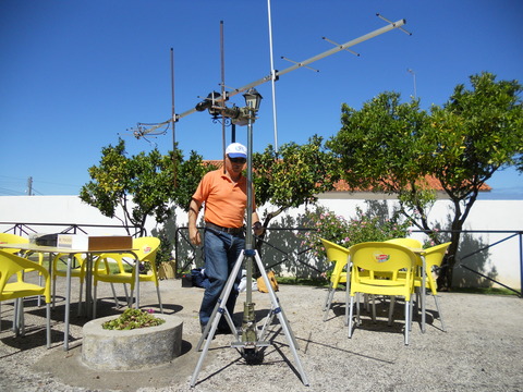
Rotor Controller
Rotor
System mount
Mother board Elevation PCB in the place of the controller button
Azimuth PCB in the place of the controller button Aspect of the PCBs in a old PC metalic box.
We used the 12 V PC power
supply.
THE KIT
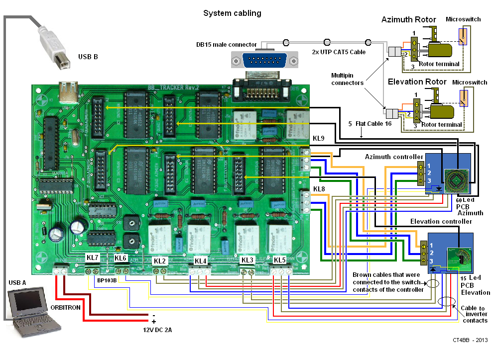
1- Five Flat cables with connectors
2- Male and female cable connectors with 5 male and female pins for the CAT5
UTP cable of command cable
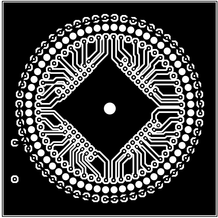
3- 60 leds Azimuth PCB with screws and nuts to fix it in the Azimuth
controller.
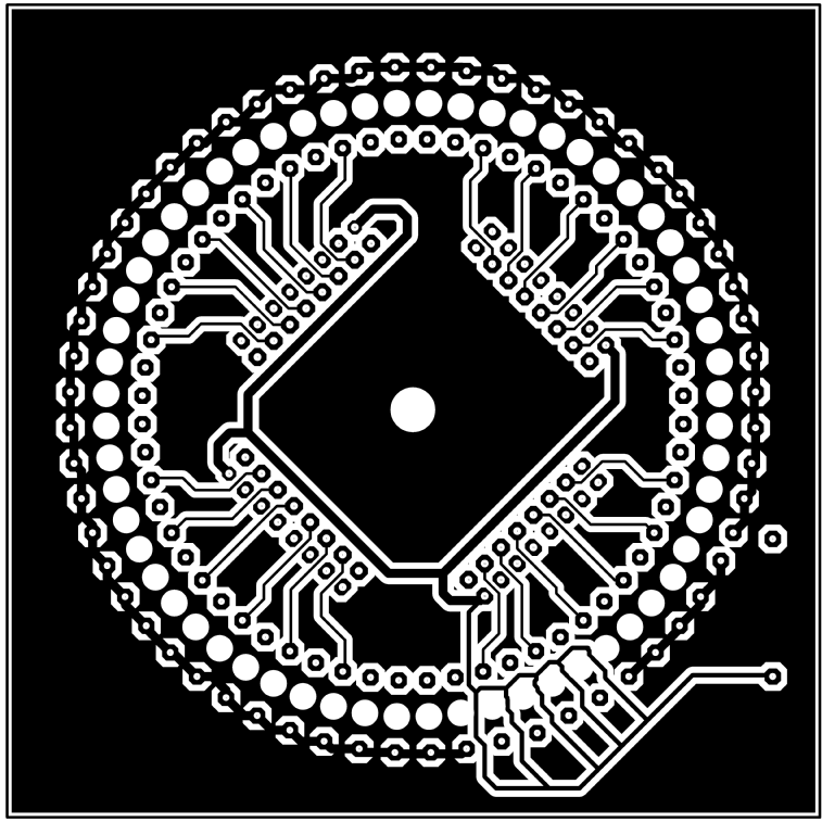
4- 15 leds Elevation PCB with screws and nuts to fix it in the Elevation
controller.
5- Two microswitches with pins to fix in the rotor as explained in the manual
of KIT assembly
6- 15 Pin Male DB Connector to connect the command cable to the Mother Board.
7- Two fototransistors BP103 B to mount in the rotating disK of the
controllers
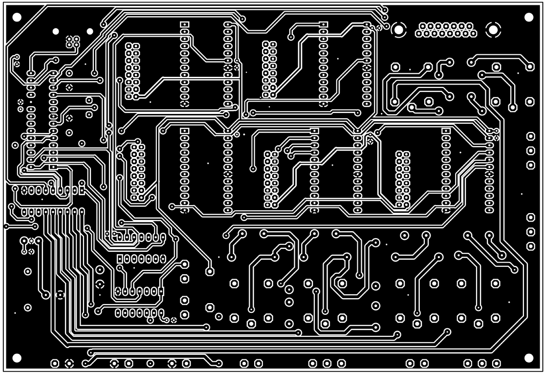
8- Mother Board PCB with microcontroler
All this parts are assembled as explained in the MANUAL ASSEMBLY
( in preparation).
